

Step-by-Step Guide
introduction
CNC cutting machines are typically designed for cutting two-dimensional designs and include two axes, X and Y, used for cutting materials such as metal, wood, plastic, and others. These machines may also feature a Z axis, which adjusts the cutting nozzle’s distance from the workpiece surface. However, the Z-axis control in these machines is usually not automated or performed via G-Code; instead, the operator must manually adjust the nozzle’s distance. The Z-axis motors can be AC, DC, stepper, or servo motors, and depending on the type and thickness of the materials, the cutting nozzle can be equipped with air gas, plasma, waterjet, laser, etc.
Radonix Interfaces for CNC Cutting Machines
Radonix, a manufacturer of CNC controllers, has thoroughly analyzed these types of machines and designed dedicated interfaces for them. The XY-Cutter and XYZ-Cutter interfaces are specifically designed for these machines:
- XY-Cutter Interface: For machines without a Z-axis or with AC and DC motors for the Z-axis.
- XYZ-Cutter Interface: For machines with a Z-axis and stepper or servo motors.
In these interfaces, all inputs, outputs, and functions are designated with the prefix C-.
Key Features of Radonix Interfaces
- Direct execution of design files without the need for conversion to G-Code.
- The ability to select individual parts from a large file and define the sequence and direction of cutting for each piece.
- Design editing in the software with features such as Scale, Rotate, and Flip.
- Software-based correction of workpiece misalignment, especially for heavy sheets.
- Separate pauses for before, during, and after cutting.
- Reverse execution of designs and the ability to run demos without activating the cutting output.
- Execution of 2D designs on cylindrical surfaces such as pipes.
These features enable Radonix interfaces to provide more precise control and greater efficiency in the cutting process.
This interface is called XY Cutter
Radonix Interfaces for XY Cutter Machines
Radonix provides three distinct interfaces for XY Cutter machines, categorized based on the strategy and functionality of the Z Axis. This division ensures compatibility with various machine types and operational requirements. Below is a detailed explanation of these interfaces:
1. XY Cutter Interface (DC Motor-Controlled Z Axis)
The XY Cutter interface is designed for machines using DC motors to control the Z Axis. In this setup:
- The Z Axis is controlled via output links:
- C-Zfree,1 for upward movement.
- C-Zfree,-1 for downward movement.
This simple control method does not involve pulse and direction signals, making it suitable for basic XY cutting machines. Operators can activate the outputs to move the Z Axis up or down as required.
2. XYZ Cutter Interface (Manual Stepper/Servo-Controlled Z Axis)
The XYZ Cutter interface is intended for machines using stepper or servo motors in manual mode. In this configuration:
- The Z Axis is controlled via pulse and direction signals, directly connecting to the Axis control pins.
- Operators can manually adjust the Z Axis position during toolpath execution to ensure the cutting tool (e.g., plasma torch) maintains the correct height from the workpiece surface.
This interface is particularly suited for applications where manual intervention is required to maintain precision during operation.
- Interface workspace
- 1- Study about different part of interface which is named and indicated in photo it means that you should get familiar with all elements like Buttons , screen , bars , volume , values , … anything on interface you have accesses


Here’s a detailed description of each section and button on this CNC controller interface

- Online (Yellow Light): Indicates the machine’s connection status. If the controller and software are connected, it is on.If there is no communication between the controller and the software, it will be turned off or displayed in gray color.
- X Axis, Y Axis, (Green Lights): These lights show the operational status of each axis. Green typically means these axes are ready. If an axis is active, it turns on. If an axis is inactive, it remains off and appears gray
- Alarm, Emergency (Brown Lights) :If an error or any problem occurs in the connection between the controller and the motors or drives, it turns on, it remains off.Position and Speed Readouts (Right Panel)
- Position :This position is shown based on where the reference point has been selected.
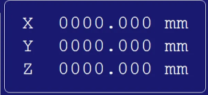
- Velocity (Below Relative Position): Shows the current operational speed in mm/s, useful for monitoring real-time movement speeds.’

Reference in Radonix Interfaces
Radonix interfaces offer a reference adjustment feature, allowing operators to redefine the Start point at any moment during the operation. This feature enhances flexibility and precision in workflows, making it suitable for diverse applications.

it means that operator can change start point of workpiece on the table.
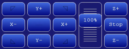
- Manual Jogging Controls :
- Arrows (X+, X-, Y+, Y-):
These buttons are used for manual axis movement (Jog) and can operate in two modes: Continuous and Incremental.
- In Continuous mode, or when the Jog key is held down, the selected axis moves at the specified speed.
- In Incremental mode, each press of the Jog key moves the selected axis by the set distance. This button works as a toggle, meaning each time it is pressed, it switches between Continuous and Incremental modes.


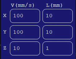
Feed Rate
In these text boxes, the axis movement speed is entered. This value is used in Continuous mode or when the Jog key is held down on the selected axis.
In Continuous mode, the speed value entered in each axis’s text box is multiplied by the Scroll percentage of manual movement (Jog).When the Jog key is pressed, the axis moves at the resulting speed.
Example:
If the value entered in the Velocity (Vel) text box for the Z-axis is 10 mm/s, and the Scroll percentage is 100%, then the resulting movement speed is 10 mm/s. Therefore, when pressing the Z+ or Z− Jog keys, the axis moves at that speed.
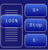
Scroll (Vertical Slider on Bottom Right ):According to figure 01-08 which is demarcated with red area or Allows for real-time adjustment of the feed rate or speed as a percentage. This control can quickly change the speed without directly altering program values.
Main Program Controls
- Settings (Gear Icon): Opens the configuration menu, where detailed settings for the CNC machine can be adjusted.

- The Exit icon allows you to close the program
- The Minus icon lets you minimize it.
- The $ icon create a report from the workpiece and operator can estimate the price

Interface specification :


This section of the interface displays the current status and features of the system. It also updates to show alarms and processes every second. For a detailed report, double-click on this section.

Main Program Controls (Bottom Center)
- Open File (Folder Icon): Opens a file dialog for loading a CAM (Computer-Aided Manufacturing) file, typically a G-code or DXF program.

This section is dedicated to controlling G-Code execution:
- RUN: This button starts the G-Code process.
- Backward: The Backward button provides operators the ability to step back within the G-Code toolpath execution process. This feature is essential for troubleshooting, rechecking, or re-executing specific portions of the G-Code.
- Pause: This button halts the toolpath.
- Reset: This button resets the toolpath.
- Inports In this section, we will investigate the structure of Inports. Essentially when Inports branch open , this kind of settings will be appeared .