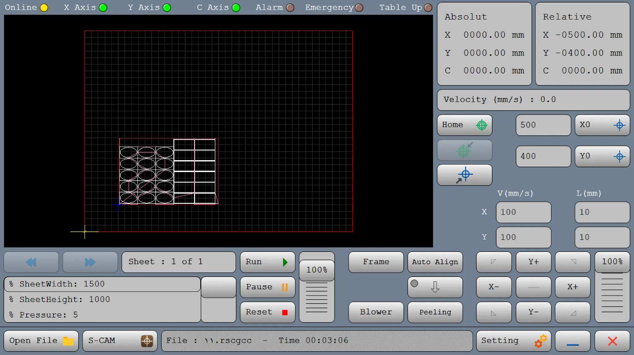
Understand the XYC SGCut interface workspace, status indicators, coordinate displays, manual motion, program controls, settings and machine-specific operator functions.
VISUAL ORIENTATION · ONE SCREEN, SIX OPERATOR ZONES
Read the workspace in 30 seconds
Start at the status strip, verify the job in the toolpath window, establish coordinates, then use the lower controls for execution, manual positioning and glass handling.
123456
1
Machine readinessOnline, axes, Alarm, Emergency and Table Up.
2
Toolpath previewLoaded sheet, design, movement path and execution view.
3
Coordinates & referencesAbsolute, Relative, Velocity, Home, X0 and Y0.
4
Program executionSheet selection, Run, Pause, Reset and speed override.
5
Motion & glass controlsJog, Frame, Auto Align, Blower and Peeling.
6
Files & systemOpen File, S-CAM, status text, Setting, Minimise and Exit.
01
MACHINE READINESS
Status indicators
Read this strip before loading or moving a job. Axis availability varies by interface and installed hardware.
X / Y / C Axis active
Each light identifies an enabled axis. If grey, check the controller-to-drive connection and confirm the drive is configured in position mode.
Alarm Drive or motion fault
Turns on for a drive error or a controller, motor or drive connection problem. Diagnose the active fault before continuing.
Emergency Safety input
Represents the configured emergency circuit. Input count and logic depend on the machine electrical design.
Table Up Table feedback
Shows the configured lifting or air-table state. Exact logic depends on the machine builder’s wiring.
Indicator colour
Colour is a quick state cue; confirm machine-specific I/O logic during commissioning.
02
JOB ORIENTATION
Toolpath, sheet and program view
The large black window confirms the correct job, scale, position and execution sequence.
Tool Path Graphical movement display
After loading a file, this area shows planned movement. Use it in simulation and production to follow machine motion and program order. Where 3D controls are enabled, select a view, zoom, or hold the right mouse button to change the viewing angle.
Sheet: 1 of 1 Sheet index
Shows the active sheet and total count. Blue previous and next controls move between available sheets or files.
SheetWidth / SheetHeight
Displays the configured glass-sheet dimensions. Confirm them before Frame or Run.
Pressure Process value
Shows configured pressure. The correct value depends on tool, glass and pneumatic design.
G-Code display Program lines
Where enabled, loaded G-code is shown and the active line is highlighted during execution.
03
POSITION & REFERENCE
Coordinates, Home and workpiece zero
Machine coordinates show where the axes are; workpiece references show where the glass job begins.
Absolute Machine position
Current axis position measured from the machine zero established by the Home sensors (machine coordinate origin).
Relative Work position
Current axis position measured from the active workpiece zero (work coordinate origin).
Velocity Path speed
Displays toolpath movement speed where configured.
Home Find machine zero
Moves slowly towards Home sensors. Use only after directions, Home speeds and sensors are verified. Shortcut: Alt + Home.
Go Zero Machine zero
Moves rapidly to an established machine zero without searching for sensors.
Go Ref Work reference
Moves axes to the stored workpiece zero.
X0 / Y0 Set work reference
Jog to the origin and press X0 or Y0 to save the current position as G54, or enter an exact coordinate in the adjacent field. Shortcuts: Alt + X; Alt + Y.
04
PROGRAM CONTROL
Run, Pause, Reset and speed
Start, hold or terminate the active job while monitoring toolpath and status text.
Run ▶ Execute or resume
Starts the loaded program. After Pause, press Run to continue from the held G-code line.
Pause ‖ Controlled hold
Stops on the current program line and retains the position for resuming.
Reset ■ Stop and reset
Stops the process and resets program execution. Recheck the job and references before restarting.
100% Execution override
The vertical percentage control beside Run adjusts execution speed. Start conservatively during verification.
05
MANUAL POSITIONING
Jog modes, speed and step distance
Manual movement combines an axis direction button, Continuous or Incremental mode and the percentage override.
CONTINUOUS MODE
Hold to move
While a Jog button is held, the axis moves at V (mm/s) multiplied by the manual override.
INCREMENTAL MODE
Press to move one step
Each press moves the axis by L (mm) multiplied by the manual override.
V (mm/s) Jog velocity
Manual speed for each axis.
L (mm) Jog distance
Distance for one Incremental move.
X± / Y± Axis direction
Moves the selected axis according to the active mode.
Diagonal arrows
Moves two axes simultaneously; each follows its own values.
Mode toggle
Changes between hold-to-move and press-to-step behaviour.
100% Manual override
Multiplies the V or L values used for Jog motion.
Example: V = 10 mm/s with 50% override produces a 5 mm/s Continuous Jog. L = 10 mm with 50% override produces a 5 mm Incremental move.
06
GLASS PROCESS
Frame, alignment and sheet handling
Machine-specific controls prepare glass position and process conditions before cutting.
Frame Verify boundary
Checks the configured outer job boundary without performing the production cut. Confirm the path fits the physical sheet.
Auto Align Alignment routine
Starts the configured automatic alignment routine. Sensor sequence and axis behaviour depend on installed hardware and settings.
Blower Sheet movement
Activates configured air support so the operator can reposition glass more comfortably.
Peeling Coating preparation
Runs the configured coated-glass preparation process where a protective layer could interfere with the diamond tool.
Table Up Table function
Operates or reports the configured lifting/air-table function.
Auxiliary / Z Optional
Some versions include auxiliary or Z-axis control. Follow the installed machine documentation before use.
07
JOB & SYSTEM MANAGEMENT
Files, status text and settings
The lower bar loads production files, reports the active job and opens configuration.
Open File Load a job
Loads supported G-code or DXF. Shortcut: Ctrl + Shift + Alt + O.
S-CAM CAM preparation
Opens the installed S-CAM/SimpleCAM workflow; available tools depend on version and licence.
File / Time / Status
Shows the interface or file, then estimated and remaining time during operation. Alarm or Emergency can turn it red. Double-click to open Form Debug and review activity, version and active alarms where enabled.
Setting Parameters
Opens Inputs, Outputs and System Settings.
— / × Minimise or Exit
Blue minus minimises CAM-Pro; red cross exits it. Do not exit during uncontrolled motion.
APPLYING CAM-PRO CHANGES
Make the change. Modify the required setting.
Press Set. Apply the value throughout CAM-Pro.
Close CAM-Pro. Exit completely after saving.
Reopen CAM-Pro. Restart to initialise the update.
08
OPERATOR WORKFLOW
A clear start-to-run sequence
Use the same order for every new job to reduce file, reference and alignment errors.
Verify statusOnline and required axes active; Alarm and Emergency cleared.
Home safelyOnly after directions, speeds and sensors are proven.
Open the jobLoad the correct G-code or DXF.
Inspect toolpathCheck scale, sheet count and position.
Set X0 / Y0Jog or enter exact reference values.
Check FrameVerify the boundary stays inside the glass.
Prepare glassConfirm Align, Pressure, Blower and Peeling.
Run & monitorUse Pause to hold or Reset to stop and reset.
XYC SGCUT · CONNECTION GUIDE
Connect CAM-Pro to the Controller
LAN connection, Windows IPv4 settings and firewall permission
Do not start motion while Online is grey or off.When communication is established, the Online indicator is active. These network settings normally need to be completed only once for the controller and computer.
WATCH FIRST
Controller IP Address Setup
Use the video together with the verified steps below. The same network principles apply to CAM-Pro, CAM-Pro Test and CAM-Pro Calibrator.
REQUIRED VALUES
Windows IPv4 Configuration
Select Use the following IP address in the Ethernet adapter IPv4 properties.
IP address192.168.11.100
Subnet mask255.255.255.0
After entering the values, select OK and close the remaining network windows.
Power the controllerConfirm the controller supply is connected and its Power LED is on.
Connect the LAN cableConnect one end to the controller LAN port and the other end to the computer Ethernet/LAN port.
Open the network adaptersStart → Control Panel → Network and Internet → Network and Sharing Center → Change adapter settings
Open Ethernet propertiesRight-click the LAN/Ethernet connection used by the Radonix controller and select Properties.
Select TCP/IPv4Select Internet Protocol Version 4 (TCP/IPv4), then select Properties.
Enter the fixed network valuesSelect Use the following IP address, enter 192.168.11.100 and subnet mask 255.255.255.0, then select OK.
Allow Radonix software through Windows FirewallWhen Windows asks, tick the available network options and select Allow access for CAM-Pro, CAM-Pro Test and CAM-Pro Calibrator.
Verify communicationLaunch CAM-Pro. The controller LAN LEDs should be on or blinking and the interface Online indicator should become active.
Official Radonix software installation and IP address guide
The source PDF includes the original connection figures and Windows Firewall sequence. Connection guidance is on document pages 46–49.